Build a Pocket Optocoupler Tester for Fast Diagnostics
2026-06-09 | By Rinme Tom
License: General Public License Signal Isolation Arduino
Build a pocket-sized tool to verify 4-pin and 6-pin optocouplers in seconds
Optocouplers are widely used in power supplies, industrial controls, motor drives, and microcontroller interfaces because they provide electrical isolation between circuits. Although these devices are generally reliable, they can fail without showing any visible signs of damage. An optocoupler may look perfectly normal while its internal LED or output transistor has stopped functioning.
When troubleshooting electronic equipment, a standard multimeter can only provide limited information about an optocoupler's condition. A dedicated tester offers a faster and more practical way to determine whether the device is working correctly before it is installed in a circuit.
This project demonstrates how to build a simple battery-powered optocoupler tester that provides an instant visual indication of device health using two LEDs. The tester supports both 4-pin and 6-pin DIP optocouplers and can be assembled using inexpensive, commonly available components.
Why Build an Optocoupler Tester?
Testing optocouplers individually can save significant troubleshooting time. A failed optocoupler can prevent communication between circuit sections, stop switching operations, or create intermittent faults that are difficult to diagnose.
This tester verifies two critical functions:
The internal input LED is operating correctly.
The output phototransistor responds to the emitted light.
By checking both stages simultaneously, the tester provides a more meaningful result than a basic continuity test.
How the Circuit Works
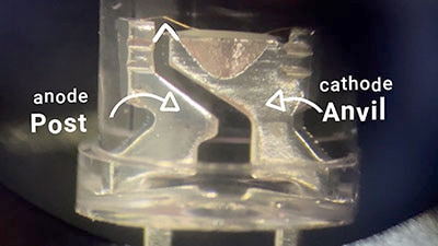
An optocoupler contains two electrically isolated sections inside a single package. The input side consists of an infrared LED, while the output side typically contains a phototransistor. When current flows through the internal LED, light activates the phototransistor, allowing the output side to conduct.
In this tester, a pushbutton applies power from a single lithium-ion cell to the optocoupler under test through a current-limiting resistor.
When the button is pressed:
Current flows through the optocoupler's internal LED.
A red indicator LED illuminates to confirm input-side operation.
Light generated inside the optocoupler activates the output transistor.
A green LED illuminates to indicate successful output-side switching.
If both LEDs illuminate, the optocoupler is functioning normally. If only the red LED turns on, the input side is working, but the output section has likely failed. If neither LED lights, the device may be defective or inserted incorrectly.
Required Components
The tester uses only a handful of parts:
1× Red LED
1× Green LED
2× 470 Ω resistors
1× Momentary pushbutton
1× 3.7 V lithium-ion battery
1× 4-pin IC socket
1× 6-pin IC socket
1× Perfboard or dot board
Using sockets instead of soldering the optocouplers directly prevents heat damage and allows multiple devices to be tested quickly.
Building the Tester
Begin by mounting the IC sockets on a small perfboard. Position the indicator LEDs where they are easily visible during testing. Install the pushbutton near the edge of the board for convenient operation.
Wire the input side through a current-limiting resistor and connect the output indicator LED through its own resistor. Verify all pin connections before applying power, paying close attention to the optocoupler socket orientation.
Because the circuit contains very few components, assembly can typically be completed in less than an hour.
Using the Tester
Insert the optocoupler into the appropriate socket, and ensure pin 1 orientation matches the socket marking. Press and hold the test button while observing the LEDs.
The results can be interpreted as follows:
Red LED ON, Green LED ON: Device passes the test.
Red LED ON, Green LED OFF: Output stage failure.
Red LED OFF, Green LED OFF: Input LED failure or incorrect insertion.
Red LED OFF, Green LED ON: Possible wiring fault or damaged output transistor.
This simple visual indication eliminates guesswork and speeds up troubleshooting, especially when evaluating salvaged or unidentified components.
Advantages of a Dedicated Tester
Compared with using only a multimeter, a dedicated tester provides several benefits:
Verifies both input and output operation.
Delivers instant pass/fail feedback.
Requires no measurement interpretation.
Simplifies batch testing of multiple devices.
Reduces troubleshooting time.
While it does not measure detailed performance characteristics such as current transfer ratio or switching speed, it is highly effective for routine bench testing and fault detection.
Applications
A compact tester like this can be useful for:
Electronics repair work
Educational laboratories
Component verification before assembly
Sorting salvaged parts
Hobby electronics projects
Maintenance and field service kits
Because optocouplers are commonly found in power electronics and industrial equipment, having a dedicated tester on the workbench can prevent faulty components from finding their way into a project.
Final Thoughts
This simple optocoupler tester is an inexpensive tool that provides quick and reliable verification of both 4-pin and 6-pin optocouplers. With only a few components and a straightforward design, it offers a practical alternative to multimeter-based testing and can help identify defective devices in seconds.