Mfr Part # 5953
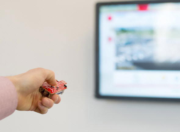
ADAFRUIT PIXEL TRINKEY - USB KEY
Adafruit Industries LLC
License: See Original Project Addressable LEDs APA102 (Dotstar) Logic Level Translator Microcontrollers WS2812/SK6812 (NeoPixel) Arduino
Guide by Liz Clark
If you find yourself feeling nostalgic for the Adalight project, then this guide is for you! You can run HyperHDR, an open-source ambient lighting system, on a Raspberry Pi and plug in a Pixel Trinkey to control NeoPixels to light up in colorful harmony with your TV or monitor. Great for immersive gaming sessions or moody movie nights.
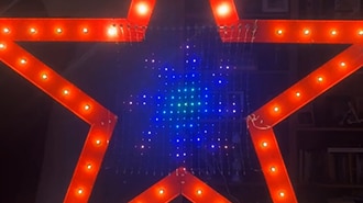
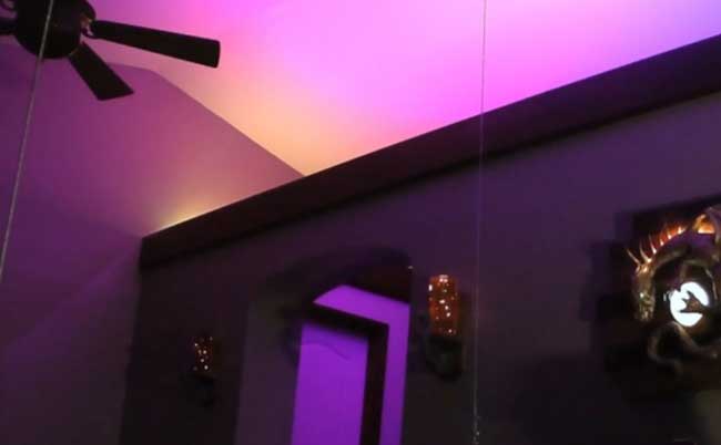
The NeoPixels are mounted at a 45° angle so that they project their color onto the wall around the TV.
HyperHDR requires two components: the host running the HyperHDR software and a device that connects to the host to control the NeoPixels via serial or SPI. In this build, a Raspberry Pi 5 is used to run the software and a Pixel Trinkey runs an Arduino script that reads a serial output over USB to control the NeoPixels. This protocol is referred to as "adalights" in the HyperHDR software.
The amount of NeoPixels you'll need will vary depending on the size of your TV. Check out the How Many NeoPixels? section on the Frame Assembly page.
Adafruit NeoPixel Digital RGBW LED Strip - White PCB 60 LED/m 4m
1 x USB Extenders
You'll need an HDMI splitter to send the video signal from your source to the HDMI capture card and your display. Not all splitters support CEC control (ex: turning your TV on/off with your streaming box remote). If CEC control matters for your setup, then make sure to get a splitter that supports it.
Consider if your setup needs HDMI CEC support. If it does, make sure that the HDMI splitter you choose supports it.
You'll build a frame that the NeoPixel strip mounts to. For this guide, 3/8-in x 2-in x 3-ft pine boards were used. The number of boards you'll need will be determined by the size of your frame. The Frame Assembly page will go over the steps to determine the size.
The amount of material you'll need for your frame will be determined by the size of your TV. The Frame Assembly page will walk you through how to determine how much material you'll need.
NeoPixel GND to Pixel Trinkey - terminal block (black wire)
NeoPixel Din to Pixel Trinkey D terminal block (blue wire)
NeoPixel +5V to Pixel Trinkey + terminal block (red wire)
The signal flow for HyperHDR can feel a little complicated if you haven't spent a lot of time routing video signals before. Here is a flow chart that explains how the setup works:
Video source (video game console, DVD player, streaming box, etc.) to the HDMI splitter input
HDMI splitter output 1 to your display (TV, monitor, etc.)
HDMI splitter output 2 to your USB HDMI capture card input
USB HDMI capture card via USB to your Raspberry Pi running the HyperHDR software
Raspberry Pi to the Pixel Trinkey via USB running the HyperHDR Arduino script
Pixel Trinkey to NeoPixels
There are two pieces of AV gear that you will need: an HDMI splitter and a USB HDMI capture card. There are recommended splitters and capture cards in this HyperHDR blog post that have been tested with HyperHDR.
For HDMI splitters, keep in mind that not all splitters support CEC control (ex: turning your TV on/off with your streaming box remote). If CEC control matters for your setup, then make sure to get a splitter that supports it. On the Overview page, there is an HDMI splitter with CEC control and one without in the parts list.
You can 3D print mounts that pair with the wooden frame made from 3/8-in x 2-in boards. The number of clips you need will be determined by the size of your frame. The STL files can be downloaded directly below or from Printables.
The wooden frame sits in the two stand pieces. The NeoPixel clips snap onto the wooden pieces.
The NeoPixel strip is secured into the channels on the clips.
The Raspberry Pi can mount to either stand piece with mounting holes.
The Pixel Trinkey uses an ATSAMD21 chip, and you can pretty easily get it working with the Arduino IDE.
Now that you have added the appropriate URLs to the Arduino IDE preferences in Arduino Setup page, you can open the Boards Manager by navigating to the Tools->Board menu.
Once the Board Manager opens, click on the category drop down menu on the top left-hand side of the window and select All. You will then be able to select and install the boards supplied by the URLs added to the preferences.
Remember you need SETUP the Arduino IDE to support our board packages - see the Arduino Setup page on how to add Adafruit's URL to the preferences.
First up, install the latest Arduino SAMD Boards (version 1.6.11 or later).
You can type Arduino SAMD in the top search bar, then when you see the entry, click Install.
Next you can install the Adafruit SAMD package to add the board file definitions.
Make sure you have Type All selected to the left of the Filter your search... box.
You can type Adafruit SAMD in the top search bar, then when you see the entry, click Install.
Even though in theory you don't need to - I recommend rebooting the IDE.
Quit and reopen the Arduino IDE to ensure that all of the boards are properly installed. You should now be able to select and upload to the new boards listed in the Tools->Board menu.
Select the Adafruit Pixel Trinkey M0 (SAMD21).
When you plug in the board, you'll need to possibly install a driver.
Click below to download our Driver Installer.
Download Latest Adafruit Drivers Package
Download and run the installer.
Run the installer! Since we bundle the SiLabs and FTDI drivers as well, you'll need to click through the license.
Select which drivers you want to install; the defaults will set you up with just about every Adafruit board!
Click Install to do the installin'.
If you get an alert that looks like
Cannot run program "{runtime.tools.arm-none-eabi-gcc.path}\bin\arm-non-eabi-g++"
Make sure you have installed the Arduino SAMD boards package; you need both Arduino & Adafruit SAMD board packages.
If you ever get in a 'weird' spot with the bootloader, or you have uploaded code that crashes and doesn't auto-reboot into the bootloader, click the RST button twice (like a double-click) to get back into the bootloader.
The red LED will pulse and/or RGB LED will be green, so you know that it’s in bootloader mode.
Once it is in bootloader mode, you can select the newly created COM/Serial port and re-try uploading.
You may need to go back and reselect the 'normal' USB serial port next time you want to use the normal upload.
Follow the steps for installing Adafruit's udev rules on this page.
The Pixel Trinkey runs Arduino code that reads serial data from HyperHDR to control the attached NeoPixels. The code is based on the HyperSerialESP32 and HyperSerialPico projects. These are maintained by the HyperHDR maintainer and work with ESP32 or RP2040-based boards respectively.
You can install the library for this project using the Library Manager in the Arduino IDE.
Click the Manage Libraries... menu item, search for Adafruit NeoPixel, and select the Adafruit NeoPixel library:
There are no additional dependencies needed for the NeoPixel library.
Before uploading the code to your Trinkey, you'll want to modify some user parameters at the top for your setup.
Update the LED_COUNT to the number of NeoPixels you are using in HyperHDR. These numbers need to match for a handshake to occur between HyperHDR and the Pixel Trinkey.
COLOR_CORRECT_RED, COLOR_CORRECT_GREEN and COLOR_CORRECT_BLUE adjust the color temperature for the RGBW NeoPixels. The default values were used with the RGBW strip from the Adafruit shop.
Update LED_TYPE for the type of NeoPixels you are using. RGBW types are suggested by the HyperHDR project. The USE_RGBW define will need to be commented out if you are NOT using RGBW NeoPixels.
Remember, the NeoPixel count in the Arduino script has to match the NeoPixel count in HyperHDR!
// SPDX-FileCopyrightText: 2025 Liz Clark for Adafruit Industries
//
// SPDX-License-Identifier: MIT

/*
 * HyperHDR AWA Protocol Implementation for SAMD21 (Pixel Trinkey)
 *
 * Based on the HyperSerialESP32 AWA protocol
 * Compatible with SAMD21-based boards like the Adafruit Pixel Trinkey
 */

#include <Adafruit_NeoPixel.h>

// Configuration - ADJUST THESE FOR YOUR SETUP
#define LED_PIN      2           // Data pin for NeoPixels (Pin 1 on Pixel Trinkey)
#define LED_COUNT    204         // Number of LEDs (must match HyperHDR config)
#define BRIGHTNESS   180         // Max brightness (0-255) - reduced to prevent washout
#define SERIAL_BAUD  2000000     // Serial baud rate (2Mbps for HyperHDR)

// Color correction - adjust these to fine-tune color balance
// Lower values = less of that color, higher = more
// Default is 255 (no correction), try 200-240 for less washed out colors
#define COLOR_CORRECT_RED    255  // Reduce if reds are too bright
#define COLOR_CORRECT_GREEN  230  // Green often needs reduction
#define COLOR_CORRECT_BLUE   240  // Reduce if blues are too bright

// LED type configuration
// For RGB strips (WS2812B): use NEO_GRB
// For RGBW strips (SK6812): use NEO_GRBW and uncomment USE_RGBW below
#define LED_TYPE     NEO_GRBW
#define USE_RGBW  // Uncomment ONLY for RGBW strips

// Protocol constants
#define MAX_BUFFER   4096        // Maximum buffer size
#define MAX_LEDS     1024        // Maximum supported LEDs

// Create NeoPixel object
Adafruit_NeoPixel strip(LED_COUNT, LED_PIN, LED_TYPE + NEO_KHZ800);

// Gamma correction lookup table (2.2 gamma curve)
#ifdef USE_GAMMA_CORRECTION
const uint8_t PROGMEM gamma8[] = {
    0,  0,  0,  0,  0,  0,  0,  0,  0,  0,  0,  0,  0,  0,  0,  0,
    0,  0,  0,  0,  0,  0,  0,  0,  0,  0,  0,  0,  1,  1,  1,  1,
    1,  1,  1,  1,  1,  1,  1,  1,  1,  2,  2,  2,  2,  2,  2,  2,
    2,  3,  3,  3,  3,  3,  3,  3,  4,  4,  4,  4,  4,  5,  5,  5,
    5,  6,  6,  6,  6,  7,  7,  7,  7,  8,  8,  8,  9,  9,  9, 10,
   10, 10, 11, 11, 11, 12, 12, 13, 13, 13, 14, 14, 15, 15, 16, 16,
   17, 17, 18, 18, 19, 19, 20, 20, 21, 21, 22, 22, 23, 24, 24, 25,
   25, 26, 27, 27, 28, 29, 29, 30, 31, 32, 32, 33, 34, 35, 35, 36,
   37, 38, 39, 39, 40, 41, 42, 43, 44, 45, 46, 47, 48, 49, 50, 50,
   51, 52, 54, 55, 56, 57, 58, 59, 60, 61, 62, 63, 64, 66, 67, 68,
   69, 70, 72, 73, 74, 75, 77, 78, 79, 81, 82, 83, 85, 86, 87, 89,
   90, 92, 93, 95, 96, 98, 99,101,102,104,105,107,109,110,112,114,
  115,117,119,120,122,124,126,127,129,131,133,135,137,138,140,142,
  144,146,148,150,152,154,156,158,160,162,164,167,169,171,173,175,
  177,180,182,184,186,189,191,193,196,198,200,203,205,208,210,213,
  215,218,220,223,225,228,231,233,236,239,241,244,247,249,252,255
};
#endif

// Apply color corrections and gamma
uint8_t applyCorrection(uint8_t value, uint16_t correction) {
  #ifdef USE_GAMMA_CORRECTION
    // Apply gamma first, then color correction
    uint8_t gammaValue = pgm_read_byte(&gamma8[value]);
    return (gammaValue * correction) / 255;
  #else
    // Just apply color correction
    return (value * correction) / 255;
  #endif
}

// AWA Protocol states (matching ESP32 implementation)
enum class AwaProtocol {
  HEADER_A,
  HEADER_w,
  HEADER_a,
  HEADER_HI,
  HEADER_LO,
  HEADER_CRC,
  VERSION2_GAIN,
  VERSION2_RED,
  VERSION2_GREEN,
  VERSION2_BLUE,
  RED,
  GREEN,
  BLUE,
  FLETCHER1,
  FLETCHER2,
  FLETCHER_EXT
};

// Frame state tracking
struct FrameState {
  AwaProtocol state = AwaProtocol::HEADER_A;
  bool protocolVersion2 = false;
  uint8_t crc = 0;
  uint16_t count = 0;
  uint16_t currentLed = 0;
  uint16_t fletcher1 = 0;
  uint16_t fletcher2 = 0;
  uint16_t fletcherExt = 0;
  uint8_t position = 0;

  // Current pixel color being assembled
  uint8_t r = 0, g = 0, b = 0;
  #ifdef USE_RGBW
    uint8_t w = 0;
  #endif

  // Calibration data for V2 protocol
  struct {
    uint8_t gain = 0xFF;
    uint8_t red = 0xB0;
    uint8_t green = 0xB0;
    uint8_t blue = 0x70;
  } calibration;

  void init(uint8_t hiCount) {
    currentLed = 0;
    count = hiCount * 0x100;
    crc = hiCount;
    fletcher1 = 0;
    fletcher2 = 0;
    fletcherExt = 0;
    position = 0;
  }

  void computeCRC(uint8_t loCount) {
    count += loCount;
    crc = crc ^ loCount ^ 0x55;
  }

  void addFletcher(uint8_t input) {
    fletcher1 = (fletcher1 + input) % 255;
    fletcher2 = (fletcher2 + fletcher1) % 255;
    fletcherExt = (fletcherExt + (input ^ (position++))) % 255;
  }

  uint16_t getFletcher1() { return fletcher1; }
  uint16_t getFletcher2() { return fletcher2; }
  uint16_t getFletcherExt() {
    return (fletcherExt != 0x41) ? fletcherExt : 0xaa;
  }
};

// Global state
FrameState frameState;
uint32_t lastDataTime = 0;
uint32_t frameCount = 0;
uint32_t errorCount = 0;
uint32_t lastStatsTime = 0;
uint16_t ledCount = 0;

// Statistics
struct Statistics {
  uint32_t totalFrames = 0;
  uint32_t goodFrames = 0;
  uint32_t showFrames = 0;
  uint32_t lastPrint = 0;
} stats;

void setup() {
  // Initialize serial
  Serial.begin(SERIAL_BAUD);
  Serial.setTimeout(50);

  // Initialize NeoPixels
  strip.begin();
  strip.setBrightness(BRIGHTNESS);
  strip.clear();
  strip.show();

  // Show startup animation
  startupAnimation();

  lastDataTime = millis();
  lastStatsTime = millis();
}

void loop() {
  // Process all available serial data
  while (Serial.available() > 0) {
    uint8_t input = Serial.read();
    lastDataTime = millis();
    processAwaByte(input);
  }

  // Timeout - clear display if no data for 5 seconds
  if ((millis() - lastDataTime) > 5000) {
    if (strip.getBrightness() > 0) {
      strip.clear();
      strip.show();
    }
  }

  // Print statistics every 5 seconds if no data
  if ((millis() - stats.lastPrint) > 5000 && (millis() - lastDataTime) > 1000) {
    printStatistics();
  }
}

void processAwaByte(uint8_t input) {
  switch (frameState.state) {
    case AwaProtocol::HEADER_A:
      frameState.protocolVersion2 = false;
      if (input == 'A') {
        frameState.state = AwaProtocol::HEADER_w;
      }
      break;

    case AwaProtocol::HEADER_w:
      if (input == 'w') {
        frameState.state = AwaProtocol::HEADER_a;
      } else {
        frameState.state = AwaProtocol::HEADER_A;
      }
      break;

    case AwaProtocol::HEADER_a:
      if (input == 'a') {
        frameState.state = AwaProtocol::HEADER_HI;
        frameState.protocolVersion2 = false;
      } else if (input == 'A') {
        frameState.state = AwaProtocol::HEADER_HI;
        frameState.protocolVersion2 = true;
      } else {
        frameState.state = AwaProtocol::HEADER_A;
      }
      break;

    case AwaProtocol::HEADER_HI:
      stats.totalFrames++;
      frameState.init(input);
      frameState.state = AwaProtocol::HEADER_LO;
      break;

    case AwaProtocol::HEADER_LO:
      frameState.computeCRC(input);
      frameState.state = AwaProtocol::HEADER_CRC;
      break;

    case AwaProtocol::HEADER_CRC:
      if (frameState.crc == input) {
        ledCount = frameState.count + 1;

        // Sanity check
        if (ledCount > MAX_LEDS) {
          frameState.state = AwaProtocol::HEADER_A;
          errorCount++;
        } else {
          // Limit to actual strip size
          if (ledCount > LED_COUNT) {
            ledCount = LED_COUNT;
          }
          frameState.state = AwaProtocol::RED;
        }
      } else if (frameState.count == 0x2aa2 && (input == 0x15 || input == 0x35)) {
        // Statistics request
        printStatistics();
        if (input == 0x15) {
          Serial.println("\r\nWelcome!\r\nAwa driver SAMD21 v1.0");
        }
        frameState.state = AwaProtocol::HEADER_A;
      } else {
        frameState.state = AwaProtocol::HEADER_A;
        errorCount++;
      }
      break;

    case AwaProtocol::RED:
      frameState.r = input;
      frameState.addFletcher(input);
      frameState.state = AwaProtocol::GREEN;
      break;

    case AwaProtocol::GREEN:
      frameState.g = input;
      frameState.addFletcher(input);
      frameState.state = AwaProtocol::BLUE;
      break;

    case AwaProtocol::BLUE:
      frameState.b = input;
      frameState.addFletcher(input);

      // Apply color to LED
      if (frameState.currentLed < LED_COUNT && frameState.currentLed < ledCount) {
        // Apply color corrections to reduce washout
        uint8_t correctedR = applyCorrection(frameState.r, COLOR_CORRECT_RED);
        uint8_t correctedG = applyCorrection(frameState.g, COLOR_CORRECT_GREEN);
        uint8_t correctedB = applyCorrection(frameState.b, COLOR_CORRECT_BLUE);

        #ifdef USE_RGBW
          // For RGBW, calculate white channel (simplified version)
          uint8_t w = min(correctedR, min(correctedG, correctedB));
          correctedR -= w;
          correctedG -= w;
          correctedB -= w;
          strip.setPixelColor(frameState.currentLed, strip.Color(correctedR, correctedG, correctedB, w));
        #else
          // For RGB strips
          strip.setPixelColor(frameState.currentLed, strip.Color(correctedR, correctedG, correctedB));
        #endif
      }

      frameState.currentLed++;

      // Check if we have more LEDs to process
      if (frameState.currentLed < ledCount) {
        frameState.state = AwaProtocol::RED;
      } else {
        // All LEDs processed, move to checksum or calibration
        if (frameState.protocolVersion2) {
          frameState.state = AwaProtocol::VERSION2_GAIN;
        } else {
          frameState.state = AwaProtocol::FLETCHER1;
        }
      }
      break;

    case AwaProtocol::VERSION2_GAIN:
      frameState.calibration.gain = input;
      frameState.addFletcher(input);
      frameState.state = AwaProtocol::VERSION2_RED;
      break;

    case AwaProtocol::VERSION2_RED:
      frameState.calibration.red = input;
      frameState.addFletcher(input);
      frameState.state = AwaProtocol::VERSION2_GREEN;
      break;

    case AwaProtocol::VERSION2_GREEN:
      frameState.calibration.green = input;
      frameState.addFletcher(input);
      frameState.state = AwaProtocol::VERSION2_BLUE;
      break;

    case AwaProtocol::VERSION2_BLUE:
      frameState.calibration.blue = input;
      frameState.addFletcher(input);
      frameState.state = AwaProtocol::FLETCHER1;
      break;

    case AwaProtocol::FLETCHER1:
      if (input != frameState.getFletcher1()) {
        frameState.state = AwaProtocol::HEADER_A;
        errorCount++;
      } else {
        frameState.state = AwaProtocol::FLETCHER2;
      }
      break;

    case AwaProtocol::FLETCHER2:
      if (input != frameState.getFletcher2()) {
        frameState.state = AwaProtocol::HEADER_A;
        errorCount++;
      } else {
        frameState.state = AwaProtocol::FLETCHER_EXT;
      }
      break;

    case AwaProtocol::FLETCHER_EXT:
      if (input == frameState.getFletcherExt()) {
        // Frame is valid! Show it
        strip.show();
        stats.goodFrames++;
        stats.showFrames++;
        frameCount++;
      } else {
        errorCount++;
      }
      frameState.state = AwaProtocol::HEADER_A;
      break;
  }
}

void printStatistics() {
  char output[128];
  snprintf(output, sizeof(output),
    "HyperHDR frames: %lu (FPS), total: %lu, good: %lu, errors: %lu\r\n",
    stats.showFrames, stats.totalFrames, stats.goodFrames, errorCount);
  Serial.print(output);

  // Reset stats
  stats.totalFrames = 0;
  stats.goodFrames = 0;
  stats.showFrames = 0;
  errorCount = 0;
  stats.lastPrint = millis();
}

void startupAnimation() {
  // Quick color cycle to show we're ready
  uint32_t colors[] = {
    strip.Color(255, 0, 0),    // Red
    strip.Color(0, 255, 0),    // Green
    strip.Color(0, 0, 255),    // Blue
    strip.Color(255, 255, 255) // White
  };

  for (int c = 0; c < 4; c++) {
    for (int i = 0; i < min((int)strip.numPixels(), 8); i++) {
      strip.setPixelColor(i, colors[c]);
    }
    strip.show();
    delay(200);
  }

  // Clear
  strip.clear();
  strip.show();
}
After updating those values (mainly the LED_COUNT variable), you can upload the sketch to your board. On boot, you'll see the first 8 pixels light up red, green and then blue. This will let you know that everything is okay on the Pixel Trinkey side of things.
The HyperHDR project has excellent documentation on how to install and use it. For this guide, you'll install it on Raspberry Pi OS, but you can reference the HyperHDR README for instructions on how to install it for Windows, LibreElec, Linux or macOS.
First, follow these instructions for setting up your Raspberry Pi. In a nutshell:
Download Raspberry Pi imager
Insert SD card in your computer
Pick device (Pi 4 or Pi 5 are good choice)
Raspberry Pi OS 64-Bit
From Customizations General:
WiFi credentials: enter your access point SSID and password
Set locale settings for your time zone and keyboard layout
From Customizations Services:
Enable SSH with password authentication
Choose your SD card from the storage options
Write to the SD card
The Pi Foundation has tons of guides as well.
After setting up Raspberry Pi OS, open a terminal window and enter the following commands:
wget https://github.com/awawa-dev/HyperHDR/releases/download/v21.0.0.0/HyperHDR-21.0.0.0-Linux-aarch64.deb
sudo apt install ./HyperHDR-21.0.0.0-Linux-aarch64.deb
sudo systemctl enable hyperhdr@pi.service
This fetches the HyperHDR release, installs it and then enables the system service for it. By enabling the service, it will automatically run on boot.
The HyperHDR GUI is available on a port on your network after setup. You can access it directly on the Raspberry Pi or on another device on your network. If you're accessing it on the Pi, navigate to this address in the browser:
http://localhost:8090/
If you're accessing it on another device on your network, navigate to this address in your browser:
http://pi.host:8090/
Update pi to your Raspberry Pi username.
After navigating to the GUI, you'll see the Overview page where you can see your system status at a glance along with the navigation menu on the left side of the screen.
There are a lot of settings for HyperHDR and there is a detailed guide available in the repository as a reference. The steps below will get you up and running with the setup used in this guide.
First, navigate to the LED Hardware section. You'll select the settings for the Pixel Trinkey and your NeoPixels. On the LED Controller tab, select these settings:
Controller type: adalight
RGB byte order: RGB
Output path: Auto
Select "High speed serial AWA protocol"
Baudrate: 2000000
If you're using RGBW NeoPixels, check off White channel calibration and enter 50% for White channel limit and update the red, green and blue values to dial in the colors. The values below were used with the RGBW NeoPixels from the Adafruit shop.
When everything is setup, click the Save settings button.
The LED Layout tab lets you configure where your NeoPixels are placed on the frame. As a result, you'll want to revisit this step after you finish assembling your frame.
You'll want to count how many pixels are going across the Top, Bottom, Left and Right sides of the frame. Enter each of those numbers into their respective boxes. The total needs to match the LED_COUNT value in your Pixel Trinkey Arduino code. If they don't then the NeoPixels will not light up.
The Input Position determines where the first NeoPixel (index 0 on the strand) is located. By default, it places it in the top left corner.
When everything is configured, press the Save Layout button to save.
Remember, the NeoPixel count in the Arduino script has to match the NeoPixel count in HyperHDR!
The Video Capturing tab is where you'll configure your USB capture card settings. To enable the capture card, check off Enable USB capture and then click Save settings.
Under the USB Capture section, you should be able to keep the default Automatic settings, but there are a lot of adjustable settings if you find you need to tweak anything.
The Effects tab lets you setup an LED effect that animates on boot. This can be handy to know that your HyperHDR instance is starting up correctly and it's recognizing your serial device and NeoPixels.
Under Boot effect, check off the box next to Activate. Then, select a Type (Color or Effect) and then a color or Effect from the dropdown below that. You can adjust the Duration (in milliseconds) as well. When you're done, click Save settings.
On the Image Processing tab, go to the Smoothing section. Select Activate and Continuous output. Then click Save settings.
Scroll towards the bottom of the Image Processing tab and you'll see the Blackbar detector section. This is an optional setting, but it can be helpful if you watch a lot of movies with black bars at the top and bottom of the screen for different film aspect ratios. If you want to use it, select Activate and increase the Threshold to 15%. Then, click Save settings.
At this point, you should see your NeoPixels lighting up in correspondence with your connected display. You can see a live feed of your image capture by clicking on the little TV icon towards the top of the menu bar.
You can click the Live video button to see a live feed of what your capture card is seeing and what color the NeoPixels should be lighting up as.
If you aren't seeing the NeoPixels light up, you can go to the Logs tab and see a detailed log of what is happening with HyperHDR. Any errors, such as not seeing the Pixel Trinkey or having issues with mounting the USB capture card, will show up here to help you diagnose any problems.
You can check the status of USB devices on your Raspberry Pi with the lsusb command in the terminal. This will list the connected USB devices.
You can also restart the HyperHDR service on the Raspberry Pi if you're having problems. Use these commands:
sudo systemctl stop hyperhdr@pi.service
sudo systemctl start hyperhdr@pi.service
A frame works best for mounting the NeoPixel strip. First, you'll need to figure out how big to build your frame.
Start by measuring the dimensions of your TV or monitor. My TV is 43 inches by 25 inches (109.22 cm by 63.5 cm). This means that the perimeter (total distance around the TV [43+43+25+25]) is 136 inches (345.44 cm).
Now that you know your display measurements you can determine how much material you need for the frame. I chose to use 3/8-in x 2-in x 3-ft pine boards for my frame. They're easily available, very affordable and easy to work with.
To figure out how many boards I needed, I took my TV perimeter (136 inches) and divided it by the length of the boards (36 inches). It came out to about 3.77, meaning that I would need four boards to build the frame.
Similarly, you will need your display perimeter to determine how long a strip of NeoPixels you need. NeoPixel strips are sold in meters, so it will be easier to convert the perimeter to meters (length / 39.37). 136 / 39.37 is 3.4544, so I'll need 4 meters of NeoPixels.
With these numbers, you can start to layout and build your frame. If you have a dimension that is longer than your material, then you can extend it with smaller cutoff pieces. For example, with my frame the horizontal edge is 43 inches long, but the stock wood is only 36 inches long. This means I cut a piece of wood that was 7 inches long (43-36) to attach to the 36-inch-long piece.
Here is a diagram I drew up in Fusion 360 to determine how I was going to assemble my frame. I decided on miter joints for the corners and to extend the horizontal pieces. If miter joints feel a bit much for you, this frame could easily be assembled with butt joints.
To cut your pieces, you could use a handsaw or a power tool like a jig saw, circular saw or table saw. Always be extra careful when you're using a saw!
For assembly, you could use wood glue or a staple gun to join the pieces together. On my frame, I used a combination of both as a test, and both held up equally well.
If you don't want to build your frame out of wood, you could try designing a 3D printed frame or looking into other materials. There are some tips here in the HyperHDR How To blog post and the original Adalights Learn Guide.
Start by laying out your assembled frame on a flat surface.
Attach the NeoPixel clips to the frame with the NeoPixel mount facing out. You'll want to have them evenly spaced around the frame.
Slide the bottom corners of the frame into the two stand pieces.
Start to insert the NeoPixel strip near where you will be placing the Pixel Trinkey. This will let you keep the NeoPixel wires short. The strip will press fit securely into the clips.
Continue to route the NeoPixels around the frame, pressing the strip into the clips.
Once you've covered the distance of the frame, align the two ends of the strip together. Determine where you want to cut the strip. Here, there was a set of contacts that aligned with the first NeoPixel, so I chose to cut there.
Cut the NeoPixel strip on the contacts between pixels.
At this point, carefully stand up the frame vertically.
Insert four M2.5 stand-offs into the front of your chosen stand side.
Mount the Raspberry Pi to the stand-offs with M2.5 screws.
Insert the Pixel Trinkey into its case.
Plug the Pixel Trinkey into the bottom USB 2.0 port on the Raspberry Pi. Insert the NeoPixel wires into the terminal block on the Pixel Trinkey:
NeoPixel GND to Trinkey - (black wire)
NeoPixel DIN to Trinkey D (white wire)
NeoPixel +5V to Trinkey + (red wire)
Plug the USB capture card into a USB 3.0 port on the Raspberry Pi. You may need a USB extender if its case conflicts with the Pixel Trinkey.
That completes the assembly! Before you place it behind your display, you'll want to do a test run to make sure all of the NeoPixels are lighting up and that everything is working as expected.
After testing, you can place the frame behind your display. Make sure to line-up the frame with the edges of your display.
When you're facing the display, you shouldn't be able to see any of the edges of the frame.
Remember, the NeoPixel count in the Arduino script has to match the NeoPixel count in HyperHDR!
This project has a lot of pieces that need to come together for everything to work properly.
Follow the HDMI Signal Diagram to route your video signal properly
Update the Arduino script with your NeoPixel count and upload it to the Pixel Trinkey. Remember, the NeoPixel count in the Arduino script has to match the NeoPixel count in HyperHDR!
Follow the HyperHDR configuration instructions
Assemble the frame, routing the NeoPixels around, and place it behind your TV or monitor
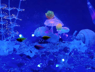
Once you follow these steps, you should see the ambient lighting flood the wall behind your TV.