ESPNOW - Peer to Peer ESP32 & ESP8266 Simple Wireless Communication Betw
2026-05-14 | By Ron Cutts
License: GNU Lesser General Public License Bluetooth / BLE Wifi Arduino ESP32
In this project, you will learn how easy it is to send data between two ESP boards using ESPNOW peer-to-peer wireless communication; you can use any ESP32 or ESP8266 board for this project.
Watch the video!
Learn more about Visuino: What is Visuino
What You Will Need
DHT11 temperature & humidity sensor (or any other DHT sensor)
Visuino program: Download Visuino


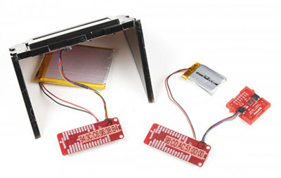
The Circuit
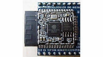
ESP32:
Connect the DHT11 VCC pin to the 5V output on the ESP32 and connect GND to ground.
Connect DHT11 PIN S (Signal) to ESP32 Pin GPIO 5
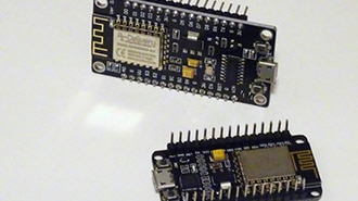
NodeMCU:
Connections are fairly simple. Start by connecting the VCC pin to the 3.3V output on the NodeMCU and connecting the GND to ground.
Connect the OLED SCL pin to the I2C clock D1 pin on your NodeMCU and connect the OLED SDA pin to the I2C data D2 pin on your NodeMCU.


Getting the MAC Address
The Visuino: https://www.visuino.eu also needs to be installed. Download the free version or register for a free trial.
Repeat this step for both ESP boards:
Start Visuino as shown in the first picture. Click on the "Tools" button on the Arduino component (Picture 1) in Visuino. When the dialog appears, select "ESP32" or "NODEMCU" Or any other ESP board that you use.
Connect pin MAC Address to Serial Pin [0] as in (Picture 2)
In Visuino, at the bottom, click on the "Build" tab, make sure the correct port is selected, then click on the "Compile/Build and Upload" button.
Then click on the "Serial" Tab and click on the button "Connect"
You should see the MAC Address as in (Picture 3), In case you do not see it, click the "Reset" button on the ESP board.
Copy the MAC Address to your Notepad as on (Picture 4)


Sender ESP32: Start Visuino, and Select the ESP Board Type
The Visuino: https://www.visuino.eu also needs to be installed. Download the free version or register for a free trial.
Start Visuino as shown in the first picture. Click on the "Tools" button on the Arduino component (Picture 1) in Visuino. When the dialog appears, select "ESP32" as shown in Picture 2


For Sender ESP32 - in Visuino Add, Set & Connect Components
Select the "ESP32 Development Board" board and in the Properties window, extend Modules>WiFi>ESP-NOW>Elements and click on the 3 dots button.
In the Elements window, drag "Device(Peer)" to the left side, and in the Properties window, paste the MAC Address of the other Board, in our case NODEMCU
Close the Elements Window
Add "Packet" component
Add "DHT11" component
Add "Analog To Analog Array" component
Select "AnalogToAnalogArray1" and in the Properties window set "Input Pins" to 2
Double click on the "Packet1" and in the Elements window, drag "Analog Array" to the Left side
Close the Elements Window
Connect "HumidityThermometer1" Pin [Sensor] to "ESP32 Development Board" Digital Pin [GPIO 5]
Connect "HumidityThermometer1" Pin [Temperature] to "AnalogToAnalogArray1" Pin [0]
Connect "HumidityThermometer1" Pin [Humidity] to "AnalogToAnalogArray1" Pin [1]
Connect "AnalogToAnalogArray1" Pin [Out] to "Packet1" > "Analog Array1" Pin [In]
Connect "Packet1" Pin [Out] to "ESP32 Development Board" Digital Pin [Sending]
Upload the Project to the Arduino Board (see the Generate, Compile, and Upload the Arduino Code step)


Receiver NODEMCU : Start Visuino, and Select the NODEMCU Board Type
The Visuino: https://www.visuino.eu also needs to be installed. Download the free version or register for a free trial.
Start Visuino as shown in the first picture. Click on the "Tools" button on the Arduino component (Picture 1) in Visuino. When the dialog appears, select "NodeMCU ESP-12" as shown in Picture 2


For Receiver NODEMCU - in Visuino Add, Set & Connect Components
Select the "NodeMCU ESP-12" board and in the Properties window, extend Modules>WiFi>ESP-NOW>Elements and click on the 3 dots button.
In the Elements window, drag "Device(Peer)" to the left side, and in the Properties window, paste the MAC Address of the other Board, in our case ESP32
Close the Elements Window
Add "UnPacket" component
Add "OLED I2C" component
Add "Analog Array to Analog" component
Select "AnalogArrayToAnalog1" and in the Properties window set "Output Pins" to 2
Double click on the "UNPacket1" and in the Elements window, drag "Analog Array" to the Left side
Close the Elements Window
Double click on the "DisplayOLED1" and in the Elements window, drag "DrawText" to the Left side & in the Properties window, set "Text" to TEMP and "Size" to 2
In the Elements window, drag "Text Field" to the left side, & in the Properties window, set "Size" to 2 & "X" to 65
In the Elements window, drag "DrawText" to the Left side & in the Properties window set "Text" to HUM, "Size" to 2 & "Y" to 40
In the Elements window, drag "Text Field" to the left side, & in the Properties window set "Size" to 2, "X" to 65, and "Y" to 40
Close the Elements Window
Connect "NodeMCU ESP-12" board Pin Received [Out] to "Unpacket1" Pin [In]
Connect "Unpacket1" > "Analog Array1" Pin [Out] to "AnalogArrayToAnalog1" Pin [In]
Connect "AnalogArrayToAnalog1" Pin [0] to "DisplayOLED1" > "Text Field1" Pin [In]
Connect "AnalogArrayToAnalog1" Pin [1] to "DisplayOLED1" > "Text Field2" Pin [In]
Connect "DisplayOLED1" Pin I2C [Out] to "NodeMCU ESP-12" board Pin I2C [In]
Upload the Project to the Arduino Board (see the Generate, Compile, and Upload the Arduino Code step)


Generate, Compile, and Upload the Code
In Visuino, at the bottom, click on the "Build" tab, make sure the correct port is selected, then click on the "Compile/Build and Upload" button.

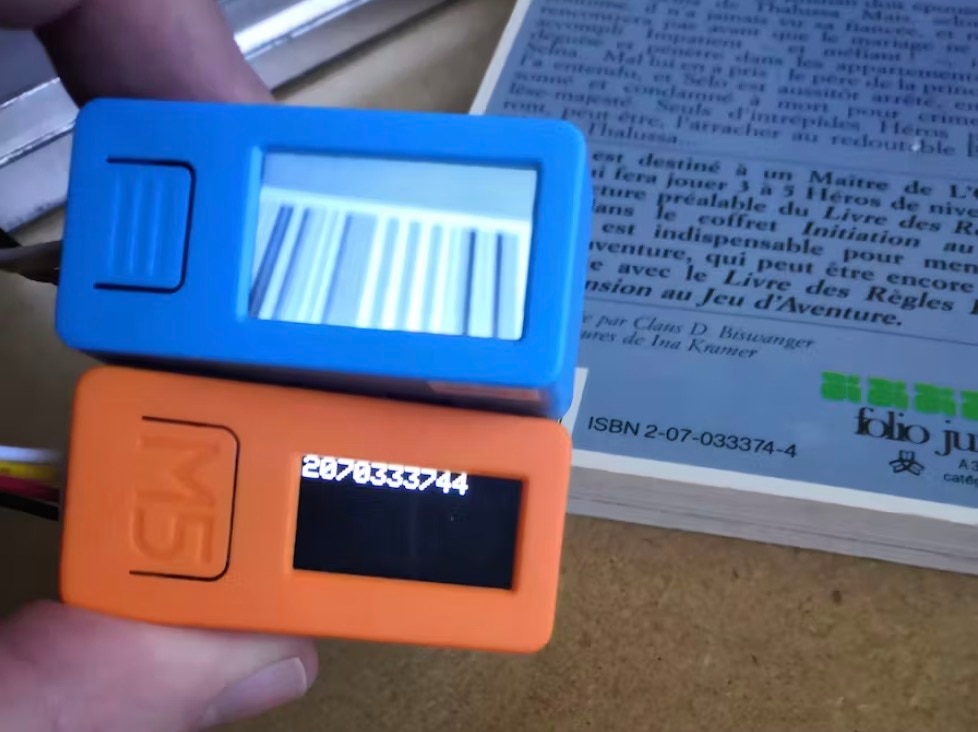
Play
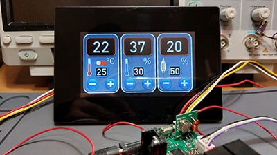
If you power the ESP modules, you should start to see on the OLED display the temperature & humidity received from the other ESP board.
Congratulations! You have completed your project with Visuino. Also attached are the Visuino project files for Sender and Receiver, which I created for this tutorial. You can download it and open it in Visuino: https://www.visuino.eu